話音和DAC
Several families of laser drivers from a variety of vendors are designed to use resistors to control the modulation and bias currents supplied by the laser driver. Potentiometers and digital-to-analog converters (DACs) can also be used to control these parameters. With each control method, there are benefits and tradeoffs that will affect the overall laser driver's performance. To fully understand the advantages and disadvantages of the choices of laser driver control systems, some familiarity with laser drivers and fiber module design is essential.
Originally, resistors were used to control modulation and bias currents, as shown on many laser driver data sheets. While the least expensive component option, resistors don't allow real-time adjustments and tweaking them during the system calibration manufacturing step is difficult and time consuming. A better solution is to use a mechanical potentiometer (variable resistor), which allows manual adjustment.
As volumes increase and automation becomes important, the mechanical potentiometers can be replaced by digital potentiometers. Digital potentiometers also offer active digital control.
Active digital control is a technique of monitoring a parameter (such as output power) by measuring it with an ADC, processing it with a digital engine, and then using this information to adjust a parameter (such as laser driver output current). Active digital engines can compensate for the temperature dependence of laser diodes.
DACs can be used in most places that a potentiometer can be used, and can offer several advantages in some designs.
The Control Section of a Laser Driver
Many laser drivers have a very simple structure that translates the programming resistance (RPROGRAM) into the output bias and modulation depth currents (see Figure 1). Typically, the internal circuitry behind the laser driver current control pins (i.e., IMOD, IBIAS) includes an internal reference voltage source. The output current of this internal voltage source is measured, and amplified via a current amplifier, the output of which is the output of the laser driver. A simple resistor connected between ground and these control pins, provides a consistent control current for that circuit. Note that the laser driver only cares about the amount of current pulled out of this pin, not the value of the resistor connected to it. Hence, the resistor can be replaced by a DAC that controls this current, as will be described later. Typically, the gain of the current amplifier is on the order of 100-200 (mA/mA), and typical output currents are up to 50-80mA.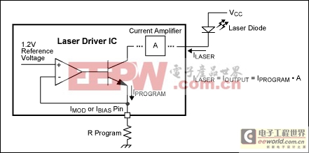
Figure 1. Laser driver internal architecture for sensing the value of the programming resistor.
Digital Pot Options (and Advantages)
Using a digital pot in place of the control resistor is the simplest and most obvious approach (see Figure 2).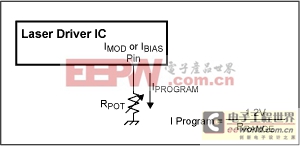
Figure 2. Programming a laser driver with a digital potentiometer.
However, the resistance value of the available pots may not precisely line up with the desired range of programming current. Additional resistors can be used to more directly map the range of the pot onto the range of the currents desired (see Figure 3). Note that the current varies with the inverse of the resistance. Digital potentiometers usually have evenly spaced steps, which means that the resulting step size of the programming current will be large in the low resistance range of the pot, and small in the high resistance range.
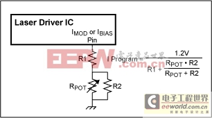
Figure 3. Programming a laser driver current with an optimized programming range potentiometer.
DAC Options (and Advantages)
A DAC can be used in place of a pot to control the laser driver currents. A voltage output DAC is used with a series resistor, such that the current drawn from the laser driver control pin is the programming current (see Figure 4). The ideal full scale/reference voltage for the DAC is the same as reference voltage internal to the particular laser driver. It can be larger, but the usable range of the DAC is compromised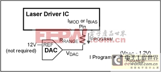
Figure 4. Programming a laser driver current with a DAC.
Some of the reasons a design engineer would consider using a DAC include:
- Linearity: The relationship between the digital code and resulting control current for the Pot is a 1/R relationship. This is a linear relationship for the DAC. The linear design has 2 primary advantages:
- 1. The DAC linear design has a very regular and predictable step size, so it is easy to calculate if the design can be calibrated to the appropriate end-target accuracy. As discussed above, the pot design can have an undesired step-size problem, due to the 1/R relationship, hence the design might not be able to hit the end accuracy.
- 2. The control algorithm used to adjust the output current based on measuring the module output power can be much simpler to design and optimize for throughput using a linear control loop software algorithm.
- Density/Board Size: In some designs, the board layout can actually be made smaller with a DAC. Since typically, there are other control parameters requiring a DAC on the board, a DAC with 2 extra channels (for the laser driver modulation depth and bias current control currents) can be chosen. Hence, the function can be fulfilled by another IC that is already required for another part of the design, rather than adding a new IC just for this purpose.
- Resolution: Pots with resolution of greater than 8 bits are not commonly available. DACs can be found with a wide range of resolutions.
- Range optimization: The full-scale voltage range of the DAC can correspond directly to the range of currents desired by the choice of the resistor. If the laser driver available programming range needs to change, with the DAC approach, the resistor is all that is necessary to change; with the POT approach, the POT may need to be changed to a different POT because the resistance value is embedded in the pot.
- Bipolar ease of implementation: If the laser driver must run from a -5V voltage rail, there are fewer pots from which to choose. Using a bipolar DAC, or similar voltage translation technique allows an alternative.
- Unit to Unit Consistency: Most digital pots have large (30% or more) error in the resistance value. DACs resistors can have errors significantly below 1%, depending on the voltage reference and resistors used. This error is trimmed out in the calibration process. However, the error needs to be taken into account in the error budget/calibration range of the calibration algorithm. Also, if it is desired to understand the distribution of required voltages to understand the control of the calibration process, the data is better if the controls are more consistent.
Conclusion
A laser module designer can use either a fixed resistor, mechanical pot, digital pot, or a DAC to control the laser driver's modulation and bias currents.The advantages of a programmable method (POT or DAC) are that the manufacturing process can be automated and digital control can be applied (e.g. to compensate for temperature).
Using POTs can be a more simple approach than a DAC. There can be a slight cost advantage to using a POT, but this is usually not significant relative to other pieces of the design.
Using a DAC can offer advantages, including improved linearity (translating to ease of software implementation and ability to hit the required accuracy), increased board density, a wider range of resolutions, a better optimization range, ease of use with a negative voltage laser driver, and unit-to-unit consistency.




評(píng)論