Lithium Coin-Cell Batteries: P
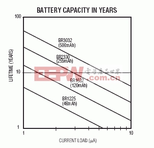
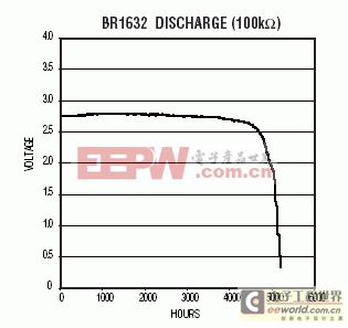
Abstract: This application note discusses various contributors to battery capacity consumption in a battery-backed application, and how to predict battery lifetime in a system. A designer should be able to use this application note to determine the battery requirements for his system. Why Battery Backup?There are several alternatives for data retention while the system is powered-off. Battery-backed SRAMs are a reliable alternative when the read-write speed or number of cycles is important. Flash or EEPROM also provide NV data storage, but at the cost of simplicity or speed. The major disadvantage of battery-backed SRAM is that the battery is a consumable. Therefore, the product selection must consider the available charge within the battery to determine the end product's lifetime. For devices that need to maintain time in the absence of system power, some form of electrical energy needs to be available to maintain a crystal oscillator. This current demand is well suited to being maintained by a battery.IC Current DemandsIf an IC (SRAM or RTC) is going to be battery powered, there needs to be a match between the current demands of the IC, the expected lifetime, and the energy available in the battery. If the IC and battery are being purchased, the data sheet specifications will provide the information required to predict the lifetime of the battery as a function of the IC load. If the IC and battery are being purchased as a module, end users can rely on the module manufacturer to have the appropriate screens in place to ensure that the system lifetime meets the specification. Figure 1. Lifetime based on amount of current being pulled from the battery. Maxim has established screening limits on all of its battery-backed products that allow the available battery capacity to power the end part for specified lifetimes up to 10 years. In the case of Maxim ICs, the design and fab processes have been optimized to produce low-current demands. In the case of higher density SRAMs purchased from outside vendors, special screening is sometimes required to ensure that the module lifetime specifications are met. Figure 1 is produced from battery capacities reported by Panasonic. The four lines shown in Figure 1 represent four of the most common battery sizes (BR1225, BR1632, BR2330, and BR3032). The battery manufacturers' rated electrical capacity (in mAh) is shown with each battery size. Battery Construction/AttributesMaxim has chosen to use primary lithium coin-cell batteries in modules that require battery backup. These cells, which have a rated voltage of 3V and a typical in-system voltage around 2.7V, make them well suited as a backup supply. The voltage also remains stable during the battery discharge (Figure 2), so the voltage at the end of life is nearly the same as with a fresh battery. While a flat discharge curve is desirable for backup supply voltage, it does make predicting the remaining electrical capacity difficult. Figure 2. The output voltage remains constant during discharge. Primary lithium coin-cell batteries have a very predictable behavior. Distributions of such key parameters as open-circuit voltage or internal impedance are very tightly grouped. These tight distributions allow the battery manufacturers to set aggressive test limits in their process to ensure that abnormal cells are excluded from the population. These tight distributions also allow the user of the batteries to identify IC/battery systems that contain a defect. For example, since the voltage distribution and the voltage vs. battery load is very predictable, the battery voltage after a load has been attached can be an indicator of the load placed on the battery. If the battery load is the current demand of a well-behaved distribution of ICs, the resulting loaded voltages will also be tightly distributed. Any loaded voltage that is seen outside of the normal distribution is then an indication of an abnormal IC or battery. This result can be used to reject the resulting module as a potential reliability risk. Battery Testing/ScreeningThe battery manufacturer's 100% testing creates an extremely consistent product. However, anyone using batteries as an integral part of his system should employ testing methods to ensure that only properly functioning cells are included in the end product. There are three types of defects that can be detected by a properly defined screen. First are the test escapes from the battery manufacturers' system. These are the easiest to detect. The second form of defect is low-level internal leakage. It is possible for a battery to have an internal defect that would manifest itself only after some period of time. Detecting these cells requires a thorough understanding not only of the proper testing levels but also the anticipated distribution of results. The third type of defect is a handling or manufacturing defect by the battery user. Because of the limited amount of electrical capacity available, inadvertent loads placed on the cell for even short periods of time can result in reduced electrical lifetimes.A thorough screening program will involve 100% tests for electrical characteristics at key steps in the manufacturing process. Because of the predictable nature of the electrical performance, measuring the battery voltage before and after load-attach will identify cells that are abnormal. Such screening also will identify loads that are not typical. In addition to the electrical screening, a visual sampling of the batteries will help identify manufacturing variations that could result in degraded leak resistance. Battery Reliability ModelThe battery is a "balanced construction" with the reactive components included in quantities that should result in full reaction. The key components to the electrical reaction are the metallic lithium, cathode, and electrolyte. The battery manufacturers' goal is to maximize the available energy placed in the cell. Since the internal volume of the battery is limited, the maximum energy density is achieved when the components are in exactly the correct ratios. Therefore, any component loss limits the available reaction of the other components. The reliability model for batteries takes the balanced construction into account and seeks to determine what will cause any key component depletion.Because the battery is a consumable in the system, the most obvious limitation of the lifetime will be an electrical load placed on the battery. The lifetime based on an electrical load is easy to calculate. Simply divide the available battery capacity in milliamp hours by the current demand in milliamps to get the lifetime in hours. Determining the battery's lifetime as a function of electrical load also requires consideration of the power-on duty cycle. In a properly designed system, the battery is electrically isolated while system power is applied. This eliminates any battery current draining or charging. The reduced duty cycle will effectively extend the lifetime of the battery in systems that are powered up a high percentage of the time and are relying on battery backup for only a short time. Because these batteries are being used in very low or zero-current applications, users also need to look for other possible mechanisms that will deplete any of the reactive components. One such mechanism is electrolyte loss through the crimp seal. This mechanism has been shown to be temperature-accelerated with an activation energy of approximately 1.0eV. At room temperature the batteries will exhibit an electrical loss rate of less than 0.5% per year, and this mechanism can safely be ignored. However, at elevated temperatures the loss rate of the electrolyte can become significant and must be considered. Because of the reactive components' balanced nature, it does not matter whether the electrical reaction consumes the electrolyte or it is expelled through the seal because of elevated temperatures. When the battery does not have enough electrolyte to continue the reaction, the battery will no longer provide current. Therefore, we recommend using a parallel model for lifetime predictions that considers the electrical demand and temperature when predicting the system lifetime (Figure 3). There are mode 相關(guān)推薦技術(shù)專區(qū)
|


評論